

Analyze with AI
Get AI-powered insights from this Mad Devs article:
Features of Raspberry Pi
So, we chose the Raspberry Pi 3B +. This is an excellent bank card-sized single-board computer. It has 4 USB ports, a WiFi module, 1GB of RAM, a BCM2835 processor with four Cortex-M53 cores, each with a frequency of up to 1.4 GHz. We decided not to use HDMI or composite output, because less wires are better. Miners will not notice and tear off the wires or they will tear it off and not notice it. The miners are quite harsh people.
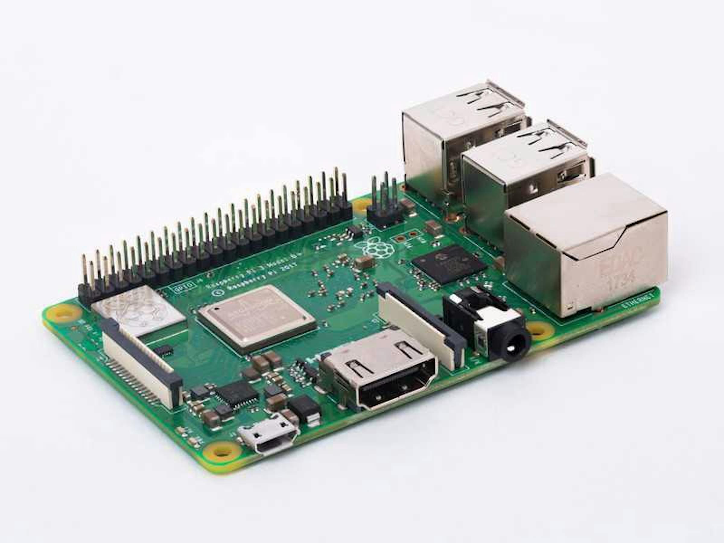
Raspberry Pi 3 B+. Image taken from https://www.raspberrypi.org
Displays
In addition to RPi, we obtained Adafruit PiTFT resistive touch displays. I liked the display at the moment I laid eyes on it. It's simple, concise, without frills. It is enough just to push it tightly onto the board to make it to work.
Well, things that are usually forgotten: power and a flash drive for the operating system (OS).
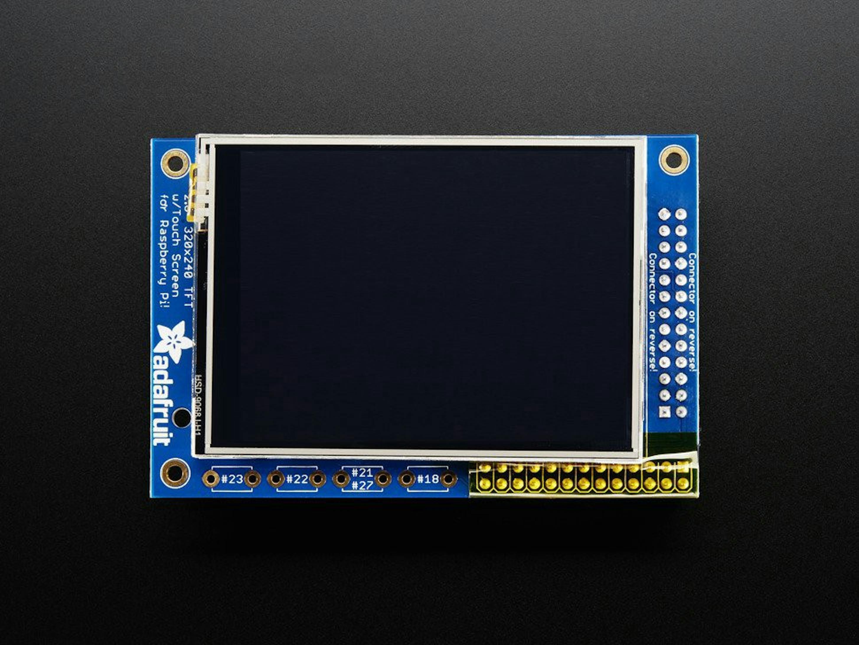
Raspberry Pi touch display. Image taken from https://www.adafruit.com
Power
At the beginning, I powered the RPi from a laptop, but something went wrong and RPi was offline. I saw blinking LEDs (the same short sequence was repeated), and suggested that it repeatedly reboots. Quickly, I asked the colleague for a phone charger and powered up the single-board to 2.5A current. It became clear that an RPi needs a strong power supply.
Flash drive
The flash drive is needed in order to write the OS image to it. Four years ago, I worked on a side project on the Raspberry Pi 2 b and foolishly took a dozen of low-quality flash drives. Flash drives worked fine on a smartphone and laptop, but not on the Raspberry Pi. However, with AData flash drives taken two days later, an RPi started to work without problems.
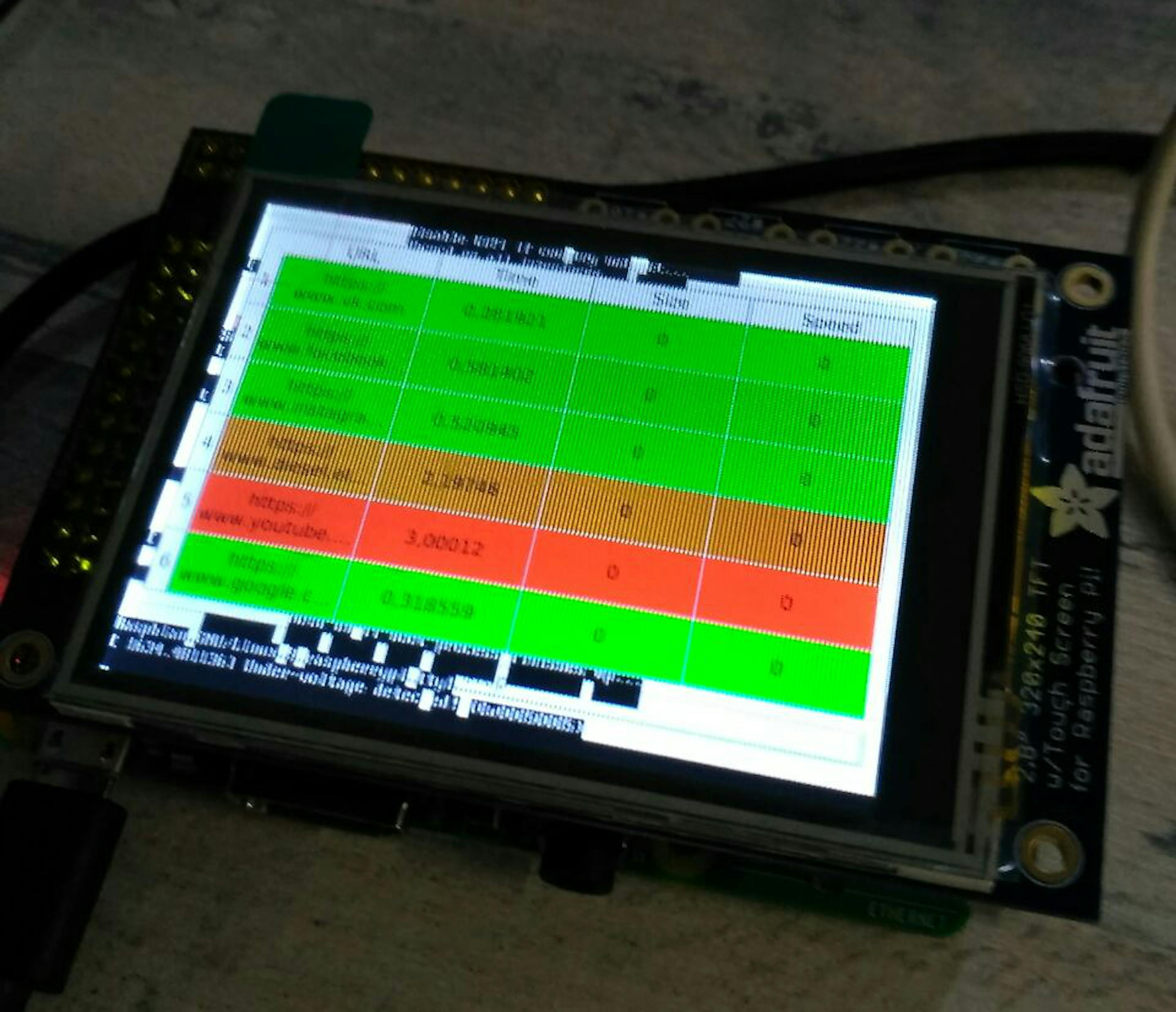
Almost completed device
Software
As a framework for the application, we decided to use Qt.
So, to implement the project in terms of software, the following steps were taken:
- Install and initial configuration of the OS on an RPi
- Turn the screen on
- Build and install of Qt
Curlinstallation- Setting up a development environment
- Ehmmm… Write the
Curler - Setting up the OS so that
Curlerstarts at OS startup and restarts in case of a crash
With all this, it was necessary to keep in mind that almost five dozen sets of RPis would have to be produced and it required quickly duplication of a flash drive.
Asus ROG GL753VD with Kubuntu OS 18.04 was used as a development PC
Stage 1. Installation and initial setup of the OS
Everything is simple here. Download the Raspbian image archive from the official site and unpack it. Copy the image using the dd utility to the USB flash drive. That`s it. The image is ready to run on an RPi. Insert the flash drive and turn the RPi on. The device victoriously blinks with LEDs.
What's next? The device doesn't know our WiFi credentials, we don't know its IP-address, and it will not allow us to access it via ssh even with a cable connection. Just by default so.
We insert the flash drive into the computer again. It will be mounted as two partitions: boot and system. The boot is small and has FAT32 file system partition and system partition with ext4 filesystem on it.
In order for a single-board player to allow access via ssh, we create a file named ssh in the boot partition. Seeing this file, RPi will allow us to log in via ssh, but only until the next reboot. After each boot, this file is deleted.
You need slightly different witchcraft to make RPi to use Your WiFI. We go into the system partition in the directory /etc/wpa_supplicant. Open the wpa_supplicant.conf file. It describes the settings for connecting to wireless networks. One network is already described there. We add a description of our WiFi network with access credentials to the new network section (the first one can be used as an example). Be sure that there is no empty line at the end of the file (once the RPi was unable to boot precisely because of this).
In order to find out the IP address of our RPi, we can use the nmap utility in this way:
sudo nmap -sP 192.168.20.0/24
Of course, you will need to substitute your own network in this command instead of mine.
We will see a list of all the hosts on the network, and if the RPi has connected to WiFi, we will find something like this in the list:
Nmap scan report for 192.168.20.49
Host is up (0.0013s latency).
MAC Address: B8: 27: EB: A0: 50: 9E (Raspberry Pi Foundation)
Well, now we can connect to the RPi via ssh:
ssh [email protected]
It will ask for a password. By default, raspberry is used as the password. It is strongly recommended you to change it immediately.
Next, to finish the configuration, you need to enable ssh access on an ongoing basis and expand the file system to the entire flash drive with the raspi-config utility. Qt takes a lot of space and just cannot fit on default filesystem partitioning.
Execute the command
sudo raspi-config
A simple application appears. Use the arrows on the keyboard to select "Interfacing Options," sub-item "Ssh." We choose the affirmative action in dialog. So, we have ssh.
Next, go to the item "Advanced Options," sub-item "Expand Filesystem," we also answer in the affirmative in the appeared dialog. We should wait a bit. Reboot the RPi:
sudo reboot -h now
It also makes sense to update all the software on the raspberry. There is a couple of commands for this:
sudo apt update sudo apt upgrade
We will wait for the completion of these commands and the raspberry is ready for use.
Stage 2. Turn the screen on
The screen simply fits onto an RPi. But tightly, nevertheless, electronics is the science of contacts.
Actually, the steps to turn on the screen in the software are described here, but it makes sense to bring them here briefly.
Run the following commands:
cd ~
wget https://raw.githubusercontent.com/adafruit/Raspberry-Pi-Installer-Scripts/master/adafruit-pitft.sh
chmod +x adafruit-pitft.sh
sudo ./adafruit-pitft.sh
A script is launched and offers us to pick settings for the screen driver.
The first dialogue gives us the choice between screen types. I have a 2.8″ resistive touchscreen.
The second dialog prompts you to select a screen rotation. For the first time, you can choose just something. And later you have to pick out the turn that you need.
In the third dialog, I noticed that I did not need HDMI.
Next, the script downloads something, installs it, thinks about something, and asks for a reboot. Note that you can run the adafruit-pitft.sh script again at any time, it will just cause a screen reconfiguration.
In general, I was very pleased with the fact that the screen wound up with a half-kick and works well even without any calibration.
After the reboot, we see that the screen shows us the console, and then the graphical she
Stage 3. Build Qt
Well, now we proceed to the very essence of the process. Why Qt at all? The reasons:
1. Allows you to build very decent user interfaces (GUIs);
2. It can be used on a wide range of OS and computer architectures;
3. Development can be easily done in C++.
The Qt build consists of four parts: preparing the environment, configuring, building, and installing.
Preparing the environment for me personally consists of creating directories with the Qt source code, a cross-compiler, a copy of the raspberry system section, and linking all this in scripts that make life easier.
I put the paths used to build the process into a separate script with environment variables.
Download the *.tar.xz archive with Qt sources from here. Unpack it somewhere.
Download the gcc compiler for ABI arm-linux-generic-elf-32bit. I use gcc-linaro-5.4.1–2017.05-x86_64_arm-linux-gnueabihf tested in battle, but you can try any one that suits the requirements of Qt.
Now we need a clone of a working flash drive from raspberry. You can make it with the dd command. We stick the flash drive into the computer and run
lsblk
We get a tree of block devices, we find the name of the flash drive. Well, we write something like
dd if=/dev/mmcblk01 of=~/images/rpi_working.img bs=100M status=progress
The path in the of the parameter you can use own. This is a matter of personal convenience.
I prefer to have a complete clone of the file system for single-board development for every significant step in the configuration. Non-global synchronization can be performed using the rsync utility.
So we have an image. You need to mount it in some directory. There is such a script for this:
mountImage.sh
The magic number 98304 was obtained by the fdisk utility. This is the offset of the system partition, indicated in the blocks of the file system in the image of the flash drive that we removed.
So, the environment for building Qt is completed.
The configuration is reduced to calling the configure script in the directory with Qt sources with the parameters we need. The parameters are selected depending on the requirements for the software being developed and the paths to various necessary pieces on a specific developer's machine. It is necessary first of all in order to identify the missing libraries for building Qt modules.
To configure Qt, I use this script like this:
buildQt.sh
It might make sense to assign a different value to the BUILDPATH variable. It specifies the directory for the shadow builds.
And these are our build_variables.sh variables:
buildVariables.sh
Only four variables are in our concern:
PATH_TO_CC — path to the compiler
RPI_ROOT — path directory with a mounted raspberry file system
PATH_TO_QT_SOURCES — directory with Qt sources
PATH_TO_QT_RPI — the path to which Qt will be installed on the raspberry.
We set them, run the script, and …
And I'm absolutely sure that Qt will not be configured. The configuration will fail due to missing libraries, even if they are in place. What to do?
After a short look at the libraries, it dawned on me that:
- There are simply no symbolic links.
- There are libraries, but they are in completely different paths
- Some libraries are not visible due to the fact that the name of the library is a symbolic link name with an absolute path. The path exists within the root filesystem of the RPi, but it is not at the root of our filesystem.
In the first case, everything is simple: we look through the configure logs, we find nonexistent libraries. If in the raspberry file system there are necessary ones with a more or less detailed indication of the version, then there is enough just a symbolic link, so we should create it manually with the ln command.
The second case is more complicated. The configure options have this: -device linux-rasp-pi3-g +. It indicates the build options for a particular type of computer. You can create your own settings for custom hardware. These files are located in the Qt source directory, in the qtbase/mkspec/devices subdirectory. There are a lot of interesting things in the qtbase/mkspecs directory. We find a file with that name, study, and edit as necessary.
But with the latter case, everything is complicated. Remaking all the links manually is extremely unreasonable, so a couple of good people wrote scripts for this tricky business and shared them with the community.
The first script is here. It's easy to stumble upon and easy to break off. It doesn`t work properly already for about three years.
The second script is here. It works like a charm.
We should run it with the root directory of RPi as a parameter (with sudo, of course). It just worked. The configurator rolls out all the features of Qt that will be in the build. If everything suits us, then we proceed to the build.
To build, go to the directory BUILDPATH and command:
make -j4
The number 4 depends on the number of cores in the processor of your computer. But you need to leave some processor for yourself, for the sake of order. Go on, make coffee, or tea. Drink it. Have a snack. Talk to someone to calm the soul. Come back. If we encounter compilation errors, it makes sense to run the assembly again. Sometimes it helps.
If errors continue to occur in the same places, then the problem can be in anything, from the compiler to missing or old headers on the raspberry. approach here is strictly individual to each build error.
If we have everything built, we can proceed with the installation.
Installation is made from the same directory BUILDPATH with the command:
sudo make install
We are waiting for the completion of the command. It copies the built libs and creates symbolic links to them.
After the installation is complete, the image is ready for use. We synchronize its contents with a flash drive either via dd or rsync utilities.
If after rsync you suddenly cannot access RPi via ssh with the error “Wrong user or password”, then most likely something happened to the /etc/shadow file. It is necessary to copy it from the flash drive section mounted on the computer to the flash drive itself.

Step 4. Install curl
Go to the RPi, execute the command
sudo apt install libcurl4-gnutls-dev
It installs curl with everything needed for development as a library.
Stage 5. Setting up the development environment
Now we want to somehow start writing application code. To do this, we must configure the QtCreator IDE. It can be downloaded and installed separately. However, we will install the whole Qt framework in order to conduct the main part of the development and debugging in comfortable conditions—on a PC. Download Qt again, but this time it's not an archive, but a full-fledged * .run file. Run it, install Qt.
Open QtCreator. Try to run some examples. If everything is well, then everything is well. However, most often the installed gcc and the libgl1-mesa-dev library are missing. Install them in the usual way for Ubuntu.
We launch some examples. Everything starts successfully and we are happy about it.
Go to Tools> Options> Kits. We see the settings for all Qt packages (namely, one so far).
Open the Debuggers tab. Add the arm-linux-gnueabihf-gdb debugger from the directory with our cross-compiler, call it arm-gdb.
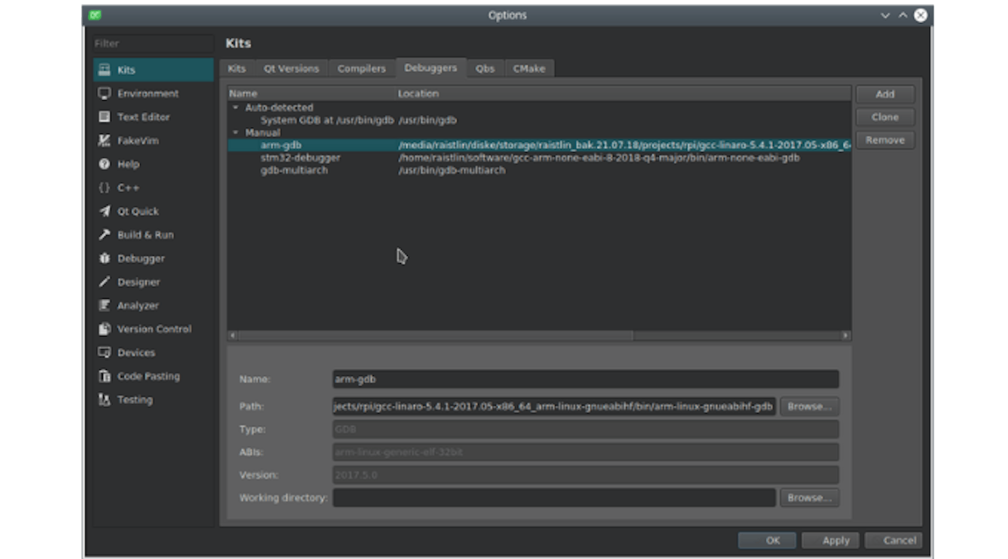
Adding a Debugger
Open the Compilers tab, add the arm-linux-gnueabihf-gcc compiler from the directory with our cross-compiler, call it arm-gcc.
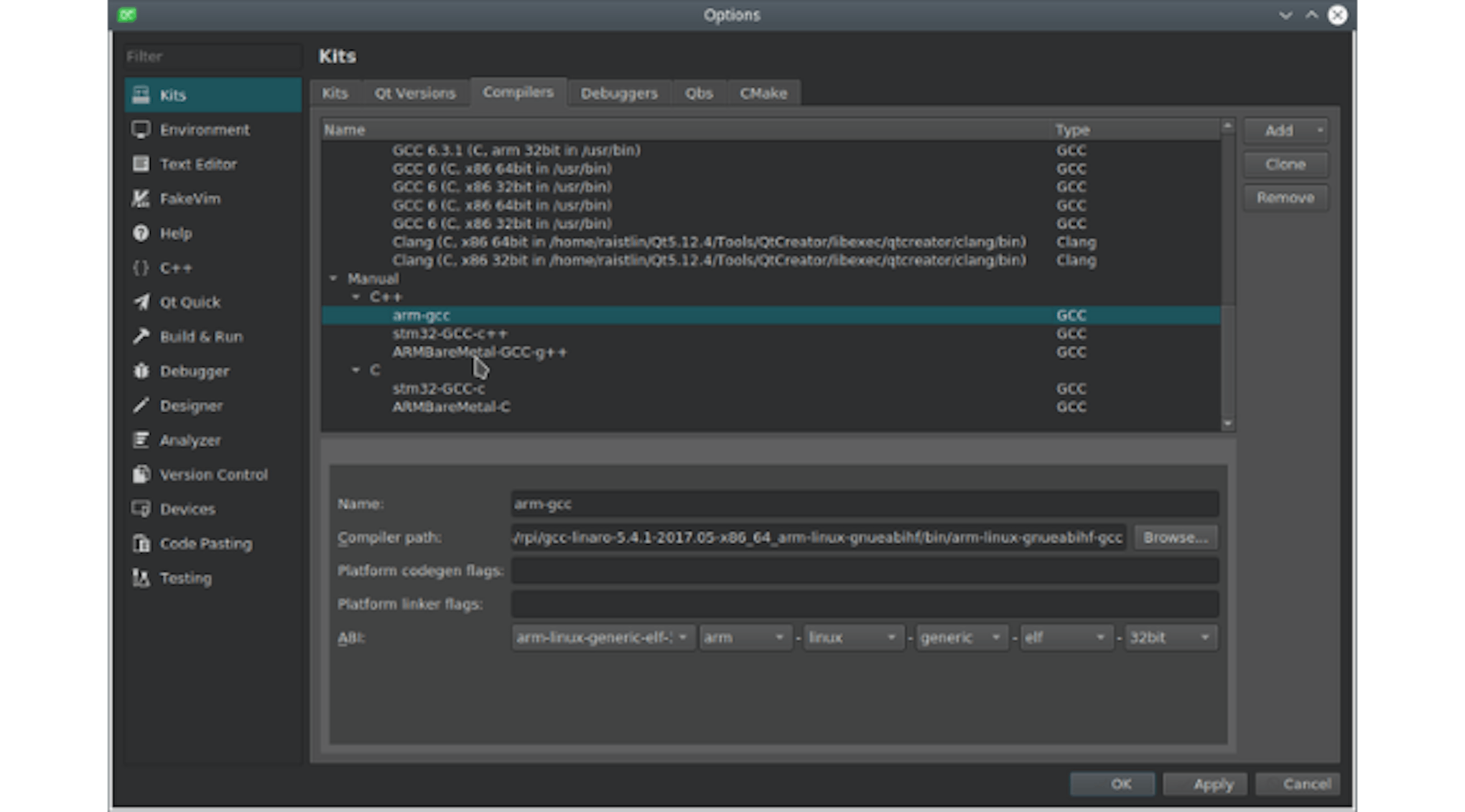
Adding a Compiler
Open the Qt versions tab, add the new Qt version from the mounted image (remember the PATH_TO_QT_RPI parameter that we saw during the build? Here in this directory on the image, in the bin subdirectory, we have qmake file, specify it), name it arm-qt.
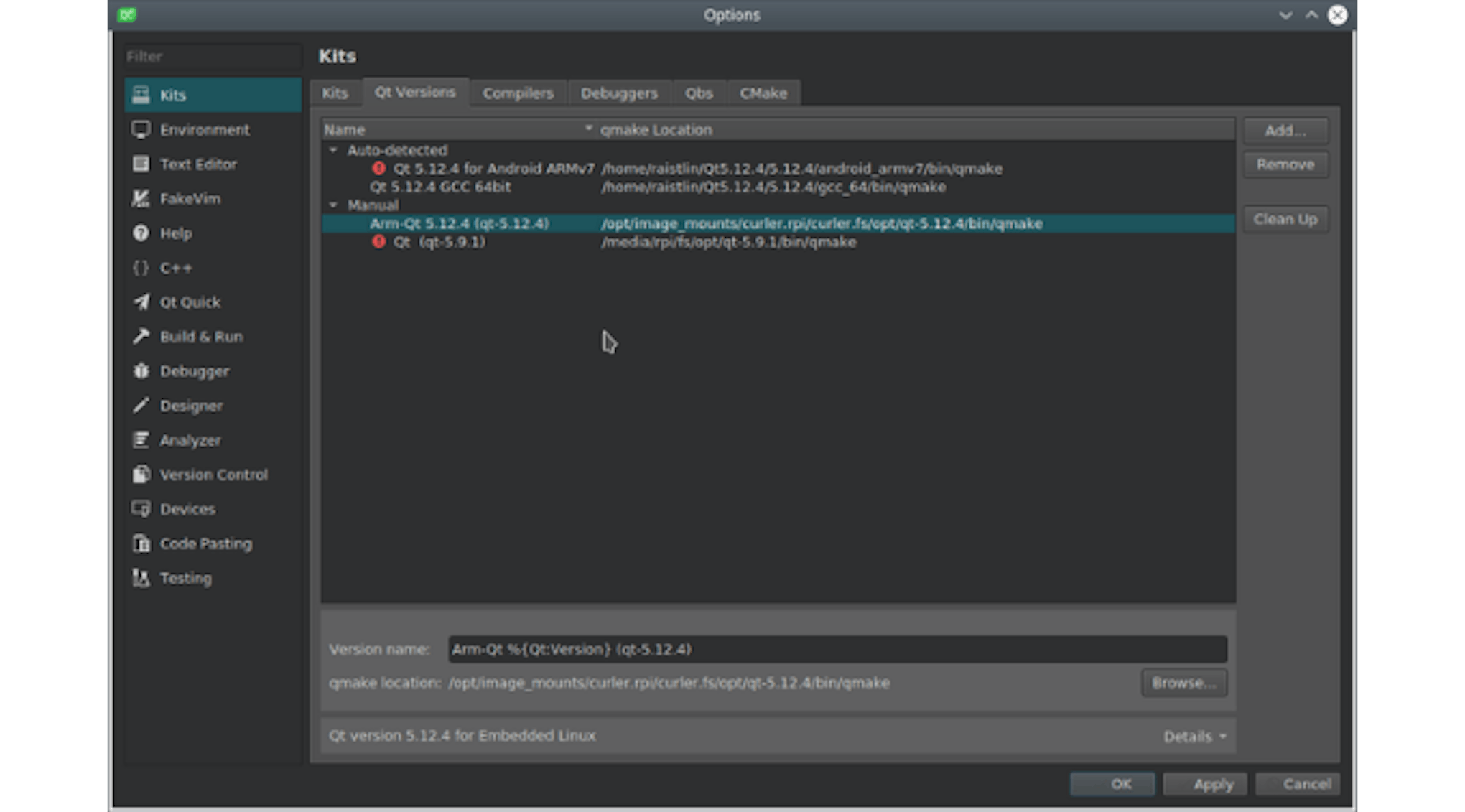
Adding a Qt Version
Apply all the changes, go to the Kits tab. Add a new kit. Call it rpi-qt. We pick in it our debugger, compiler, and version of Qt.
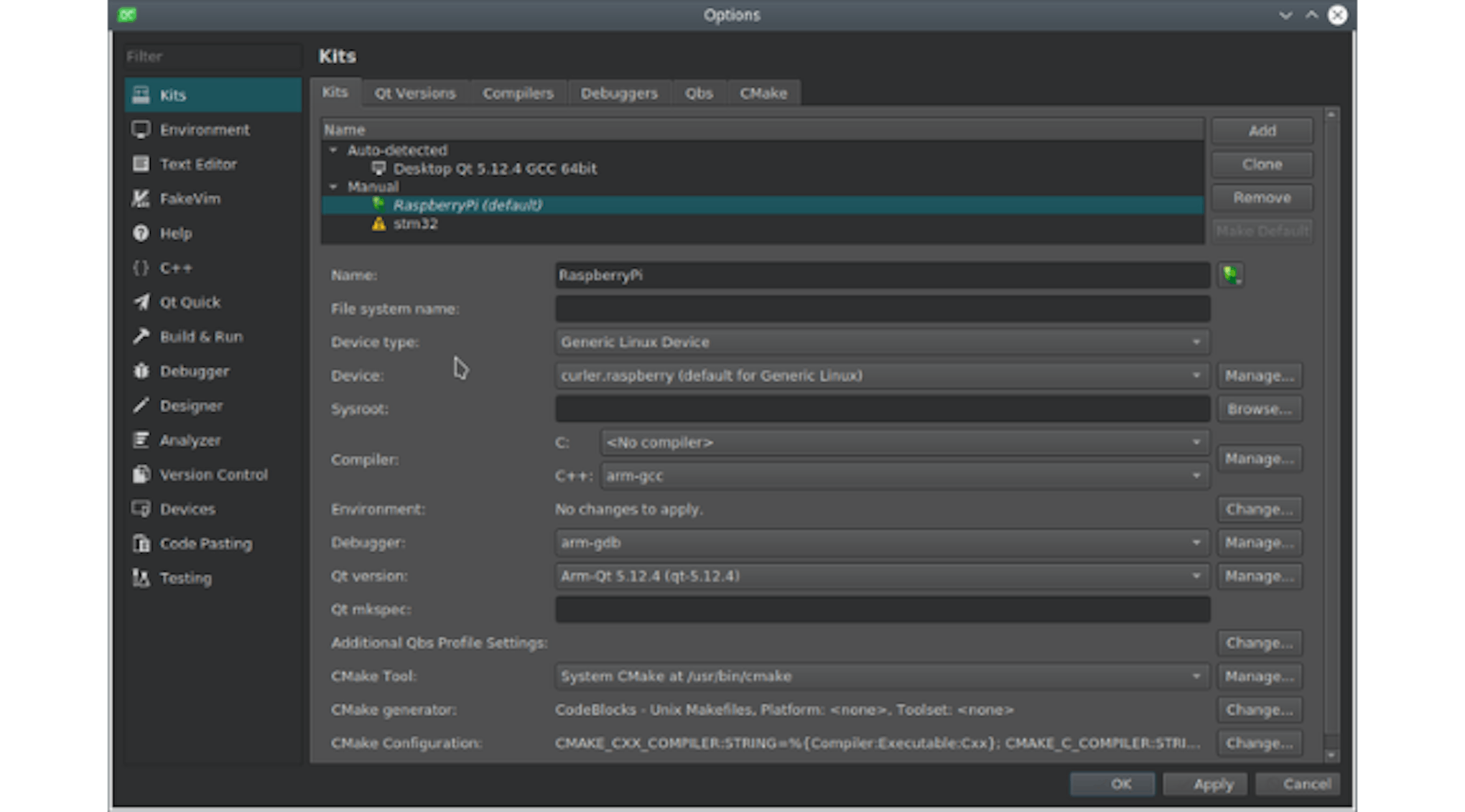
Adding a new kit
In Device type, specify Generic Linux Device, in Device, click Manage. The device management dialog opens.
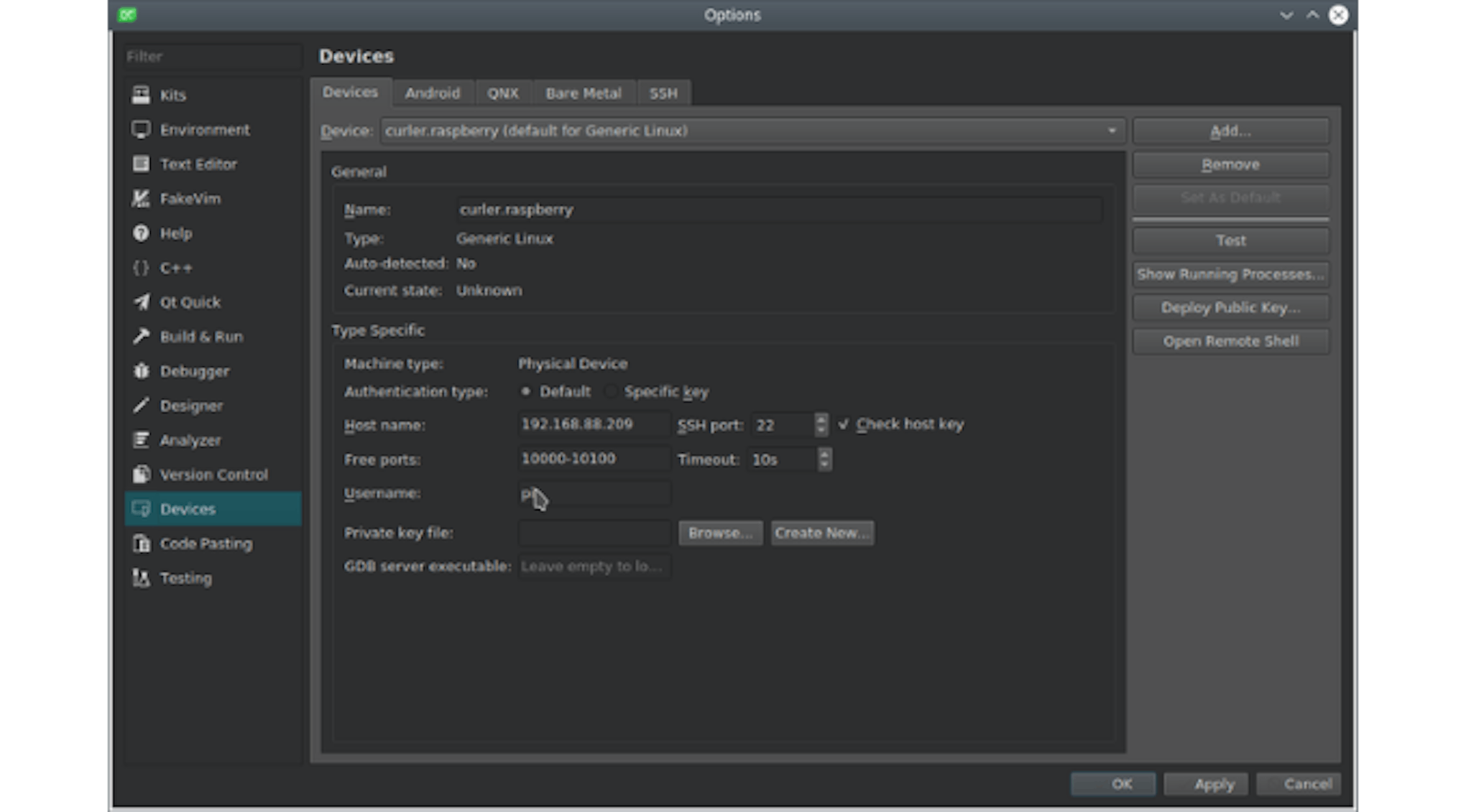
Device management dialog
Add a new Generic Linux device, call it something (here it is curler.raspberry). We write down its ip-address and username, which we use for SSH access. Click test. We see a window in which the result of the verification is displayed. We apply and close. We are again on the Kits tab. The name selection on the right has a small picture with a computer. Click there and select the icon. Less confusion will arise further.
GitHub Gist is loading...
Stage 6. Writing a program
We should create a new project, and include both sets in it (both for the computer and for the RPi).
We connect libraries in a pro-file:
Libs + = -lcurl
Well, we change the deployment rules a bit:
target.path = /home/pi/qcurler/qcurler
INSTALLS + = target
This will lead to the fact that the project will be deployed on the RPi in the home directory. Less rights issues during development will appear.
We write the code, as for regular software with Qt framework. We debug the program on the PC. If everything is fine, try to run it on the RPi. A window appears on the display with our program.
However, we needed only our program to be available, and therefore, through the raspi-config utility, we turned off the graphical shell and started the program with the parameter
-platform linuxfb
And it started on top of the console. For such programs, it generally makes sense to use launch scripts with its environment variables and parameters, but it depends on the development method.
Script to run curler
The source code of our application itself can be found here.
Step 7. Final setup - Autostart
In Raspbian, systemd is responsible for services management.
In order to register a service, you must put its description in the form of a file with the .service extension into the /etc/systemd/system directory and run the command:
sudo systemctl enable servicename.service
Where enable is the command and servicename is the name of the uploaded file.
There are a whole bunch of commands: start, stop, restart, disable. It is best to consult the systemd documentation.
To start the service you need to use the start command.
Our service description is as follows:
Curler's Service Description
Other flash drives
After we sent the first batch of devices, the suitable flashcards ran out within a radius of walking distance from the office. The taken new Chinese flash drive, quite suddenly had lesser storage size and dd simply refused to make the proper copy. There was a need to reduce the image to write it to a flash drive. This script helped us out:
GitHub Gist is loading...
Summary
The article describes my personal way of software development for a single-board Raspberry Pi computer, but in general terms, it will fit other single-board computers of a similar class. It will also be suitable for custom hardware (there was a case of using Qt on a proprietary drill rig controller), with the difference that it was more convenient for my personal working controller to boot through the NFS network file system.
If you have comments or notes, please share it.
P.S. Finally, I'll repeat the link to our repository with Curler


Latest articles here