

Analyze with AI
Get AI-powered insights from this Mad Devs article:
This article is in some way a continuation of the previous article related to inertial reference systems, but this time it is about how to assemble and make the navigator work with a microcontroller and a set of inexpensive sensors. The legitimate question is what it is needed for if almost every phone has a necessary set of sensors and compass-like applications?
- The first reason is very not obvious control. In some applications, I did not understand how to make the arrow point in the direction I need. Perhaps this is not an indicator of the application complexity.
- Some applications start showing South if you turn the phone.
- Smartphones run out of battery very quickly.
There are different analogs of such device — GPS-returners for mushroom pickers, travelers, etc. If there was no requirement to receive a direction from any device position in space, we could significantly simplify the design or suggest to try one of these existing solutions. However since one of the key features is the ability to show the direction from any position in space, we need to implement our solution from scratch.
Problem statement
There is a need to assemble a device from scratch that will:
- Show the direction from the current point and orientation in space in the direction of a predefined coordinate (for example "my home" or some local showplace).
- Have a simple interface and small size.
- Be powered by battery and work without recharge for at least 1 month.
- Be intended for "economy" sector of the market.
Taking into account the requirements above, I think it would be nice to make the device show current date and time, charge level and an alarm clock on board. Additionally, I added a bootloader in order to facilitate the firmware update and replacement of target coordinates via USB with the ability to work from a battery with charge and gauge controller. Yet the most important requirements are small size, low current consumption, and accurate navigation.
Bearing calculation
In order to show the direction somewhere, you need to know only 2 things — our actual position and orientation in space. Knowing the current coordinate one can get the azimuth by solving the inverse geodesic problem.
The geodesic task is related to the determination of the relative position of points on the Earth’s surface and is divided into a direct and inverse problem. The direct geodesic task is called the calculation of geodetic coordinates — the latitude and longitude of a point lying on the Earth’s ellipsoid, the coordinates of another point and the length and azimuth of the geodesic line connecting these points. The inverse problem is to determine, by the geodetic coordinates, two points on the Earth's ellipsoid of length and azimuth of the geodesic line between these points. Depending on the length of the geodesic line connecting the points in question various methods and formulas developed in geodesy are used. According to the size of the accepted earthly ellipsoid, tables are compiled which facilitate the solution of the geodesic task and are designed to use a certain system of formulas.
Current orientation calculation
To determine the current orientation I use Madgwick filter — an open-source project designed primarily for the low computing power of the target system. As inputs, it uses the readings of the accelerometer, gyroscope, and magnetometer. The output is a quaternion which describes the orientation of the device in space. For a better understanding of quaternions use this resource. The filter works really fast — on my 24MHz controller it updates 360 times per second given that time is still being spent on getting data from the sensors. It almost does not waste resources (the documentation states that 160 addition operations, 172 multiplication, 5 divisions, and 5 square root extracts are used) and has only 2 parameters: the sensor sampling frequency and the gain factor. The function could be modified to use not the frequency of data acquisition, but calculate the time difference between two measurement portions. This improves filter performance. The gain must be selected in the search of a compromise between the rate of stabilization of the filter and its accuracy.
Where should the arrow point to?
Knowing the azimuth and the current position of the device in space we can determine the angle by which the arrow must be turned so that it points in the right direction. In this implementation 2 angles are used at once: dX and dY (respectively the angle by which the X and Y axes are to be rotated). Two angles are needed since if one of the axes suddenly coincides with the Z axis, the second angle is used.
This is how it looks in normal mode of operation, when the device shows where it is needed, i.e. angle dX = 0.
Surely, there are more simple and accurate ways to calculate the angle dX. If you have suggestions on how this could be improved, please post in the comments.
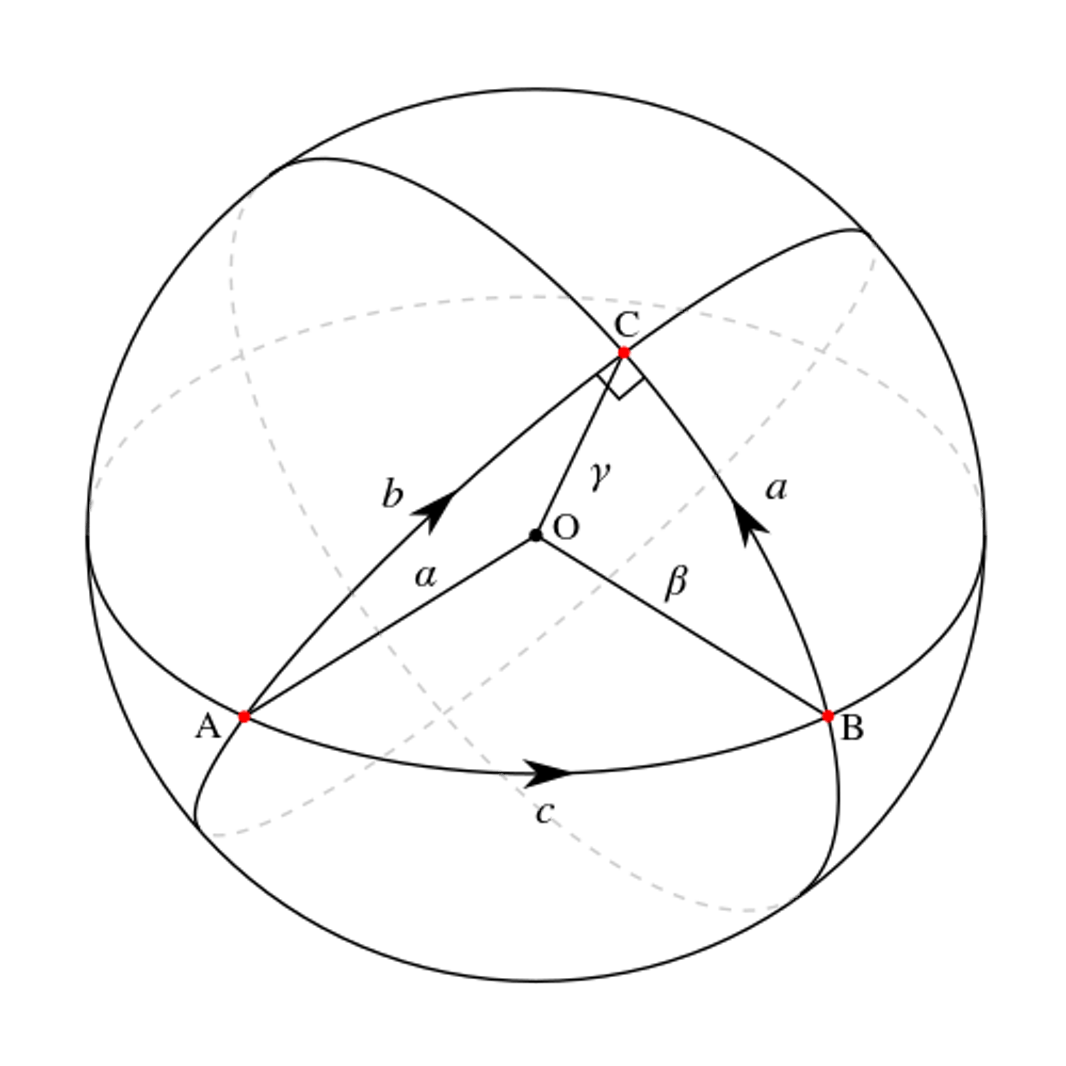
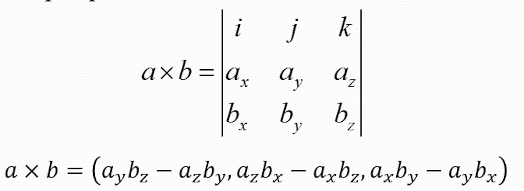
So, we have a quaternion that describes the current position of the device in the global coordinate system and the azimuth. Let's denote the quaternion of the current position by qCurrent. Take the projection of the unit vector onto the X axis and denote it by iX. Turning the iX with qCurrent quaternion we get the vector srcX. If we rotate iX by the value of azimuth then we get the vector dstX. The difference between these vectors needs to be displayed to show destination direction. The dot product of vectors is used to determine the angle between these vectors.
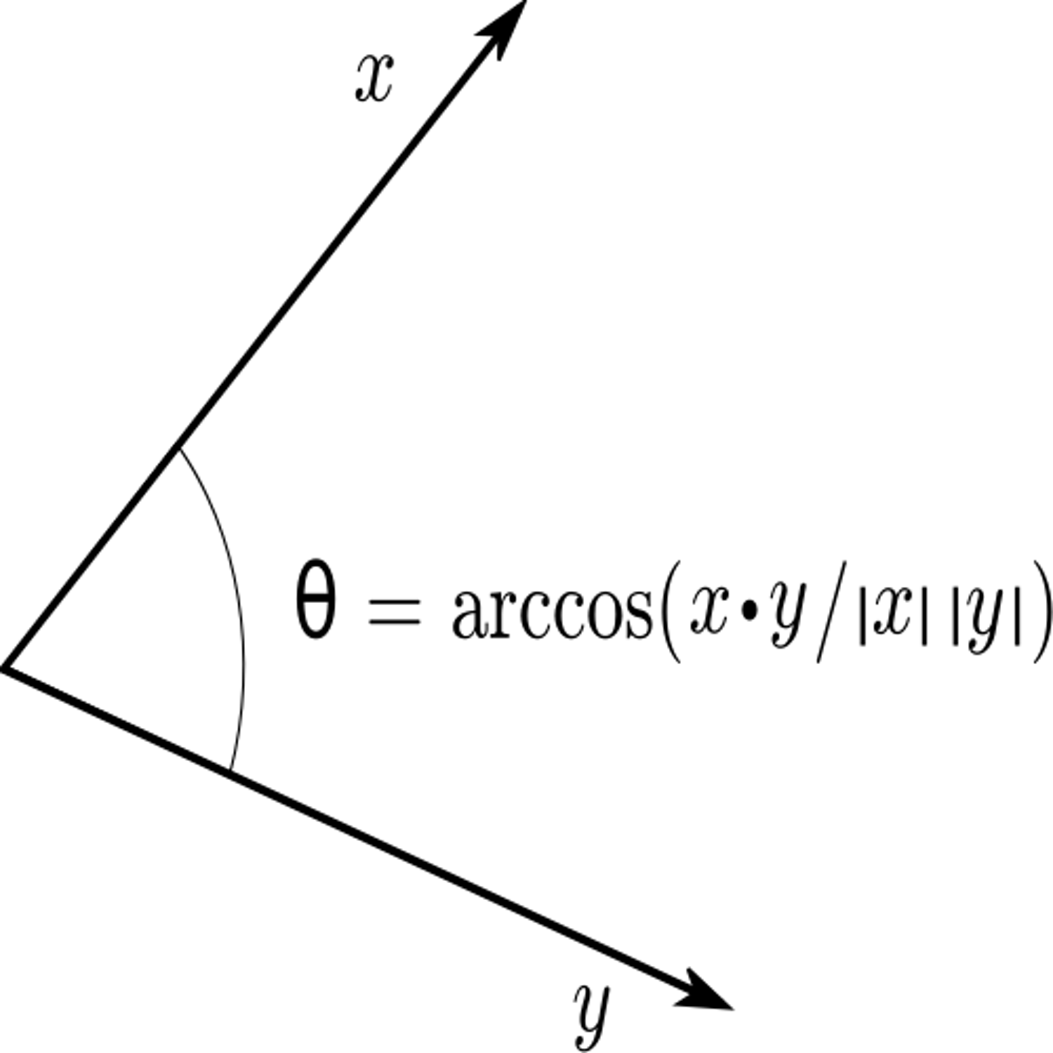
By BenFrantzDale at the English Wikipedia, CC BY-SA 3.0, https://commons.wikimedia.org/w/index.php?curid=49972362
To determine the sign of the angle, I used the cross product of vectors, more precisely, the sign of the determinant.
Got from here: https://ru.onlinemschool.com/math/library/vector/multiply1/
Actually, this is where all the mathematics of the project ends :). We have an angle to which we need to turn the display arrow so that it points in the right direction. Moreover, if dX is equal to 0, then the component of yaw (can be calculated) of the current quaternion will be equal to the azimuth found.
Used components
We decided to use ARM as a controller for many reasons, the main of which is profitability. They are cheap, 32-bit, have flexible power settings, etc. The choice fell on STM32F100RBT6. I had the debug board of this particular model available; the controller was quite suitable for the characteristics. Unfortunately, there is no USB hardware on it; otherwise, it would be even easier to make a bootloader. Also, there are more interesting models in terms of current consumption (series L, for example). But compared to how much GPS consumes, the difference is not very noticeable :) The remaining components were selected as available in our city. The first set of modules looked like this:
- MCU stm32f100rbt6
- LCD display Nokia 5110
- Accelerometer + gyroscope MPU6050
- GPS receiver Neo-6M
- Magnetometer LIS3MDL
In the final version, the magnetometer was replaced with a QMC5883L. This was due to the fact that I had burned all the LIS3MDL magnetometers. I do not know how to call this phenomenon differently. One of the modules immediately stopped responding on the I2C bus, and the other 2 gave out random data. These magnetometers were used in the form of modules from the Russian manufacturer, which I will not name. But, apparently, these modules can only be used with controllers that operate from 5V, not from 3.3V. The documentation, of course, says that you can use it anyway, but in fact, you can't.
With QMC5883L, too, the friendship did not start immediately. I ordered the magnetometers HMC5883L. When I began to request data at the address 0x1E, I received an error that there is no device with such an address on the bus (got NACK after I2C start condition). Having quickly assembled an I2C scanner, I made sure that some device has the address 0x0d. It turned out that the cases are similar and often take the QMC for the HMC. If suddenly someone wonders why his HMC does not respond, keep in mind this info.
GPS is used only for 2 things:
- Time correction, if the difference with the value in the RTC (embedded real-time clock) is more than 5 seconds.
- Correction of its own position and azimuth.
In the final version of the firmware, the GPS receiver will be turned on only upon user request in order to save battery.
Most likely, we will replace the display with an OLED and improve the backlight.
Hardware part
I must say that the layout of the PCB in Kicad looks much better. Here is a diagram for purely informational purposes.
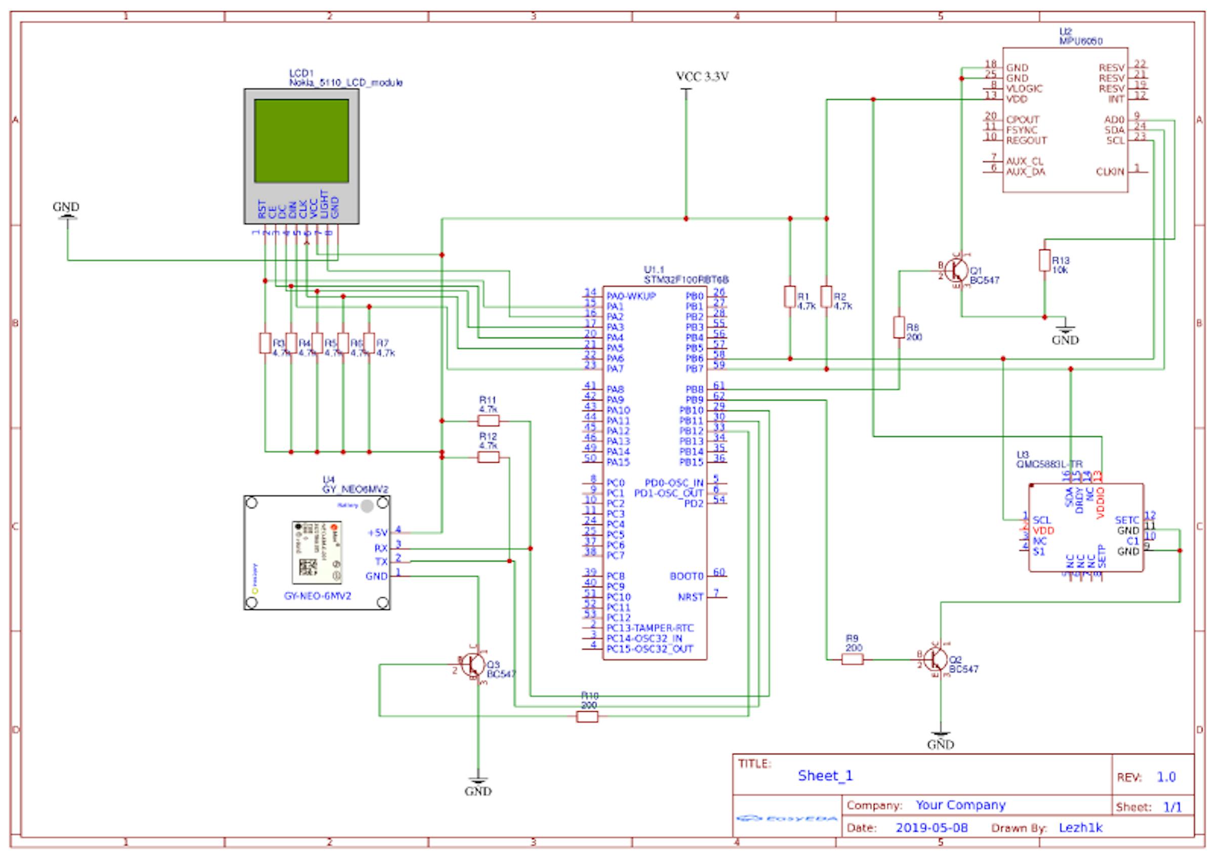
Made with easyeda.com

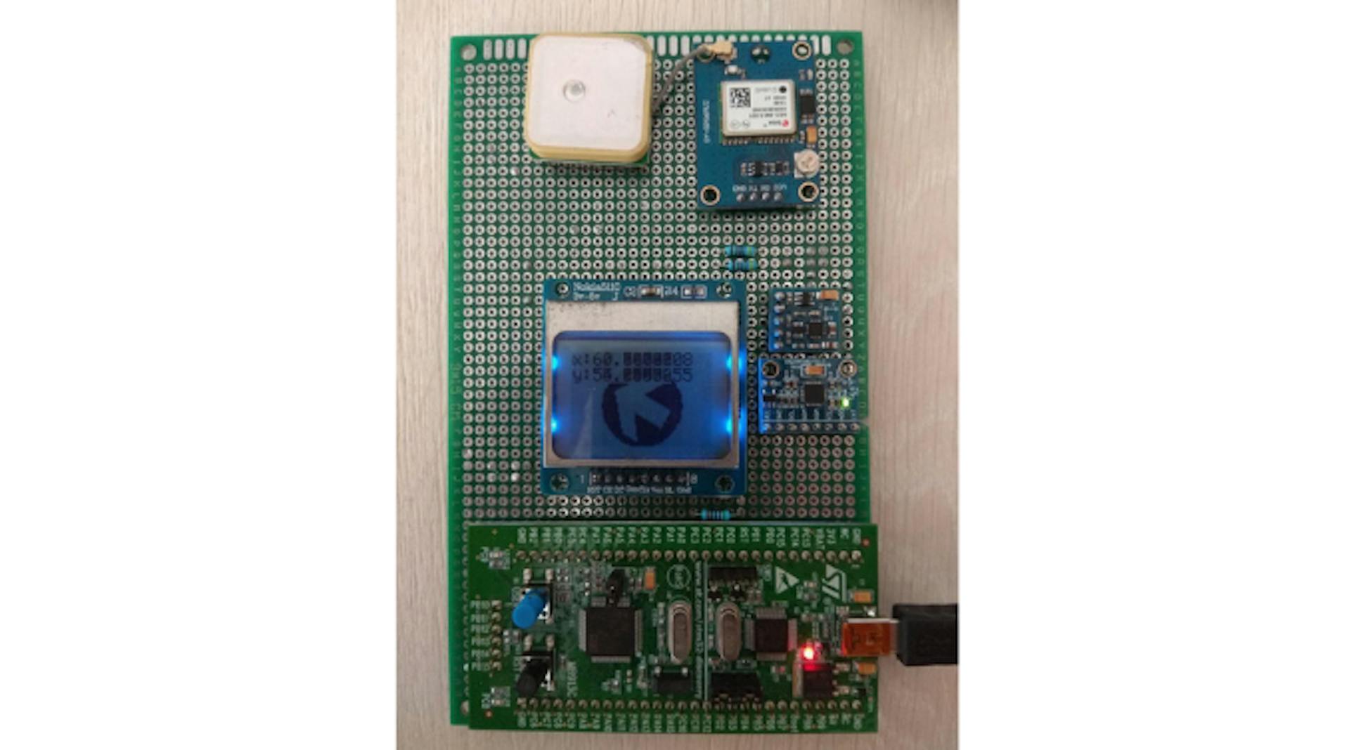
The result is the following:
- Display communicates with the controller via SPI.
- Magnetometer, accelerometer, and gyroscope use the I2C bus.
- GPS receiver sends data via USART3.
Each of the components is connected through a transistor, which gives me the ability to turn on/off devices as needed. It would be possible to power the magnetometer and gyroscope from the legs of the controller, but the current of 5mA seemed rather large to me. The documentation states that IO pins can withstand up to 20mA, but in fact, the controller sometimes just reboots. It was fixed with a good stabilizer and proper power wiring, so that the transistors for the magnetometer and gyroscope remained simply as a historical element.
What's wrong with I2C in STM32F100?
As was mentioned above, the magnetometer, accelerometer, and gyroscope communicate with a microcontroller via the I2C bus.
I2C ensures good performance with the relative ease of development. There are 2 modes:
- Normal mode — speed up to 100KHz
- Fast mode — speed up to 400KHz
I2C uses two wires that are pulled up. One of them is for data, and the other is the clocking line (SDA and SCL). There are a lot of detailed specifications on the Internet and descriptions of what kind of bus it is and how it works, so we'll go straight to the implementation features in the STM32F100X controllers.
Main bus characteristics:
Any device on the bus can be a master or a slave
In Master mode implemented:
- Clocking signal generation.
- Start/Stop signal generation
In Slave mode implemented:
- Address verification mechanism
- Using two slave addresses
- Detection of the stop bit issued by the lead to the line
- Generation and definition of 7/10 bit addresses
- Support of different baud rates
- The presence of multiple flags that signal events, as well as errors on the line
Work in one of the following modes is possible:
- Slave receiver
- Slave transmitter
- Master receiver
- Master transmitter
The default mode is slave, but as soon as the device generates a start-bit, it immediately turns from slave to master.
In our case, only 2 modes are used: Master receiver and Master transmitter. Moreover, as a transmitter, our controller is used only for initializing and configuring modules.
Of course, that all events I2C can generate own interrupt.
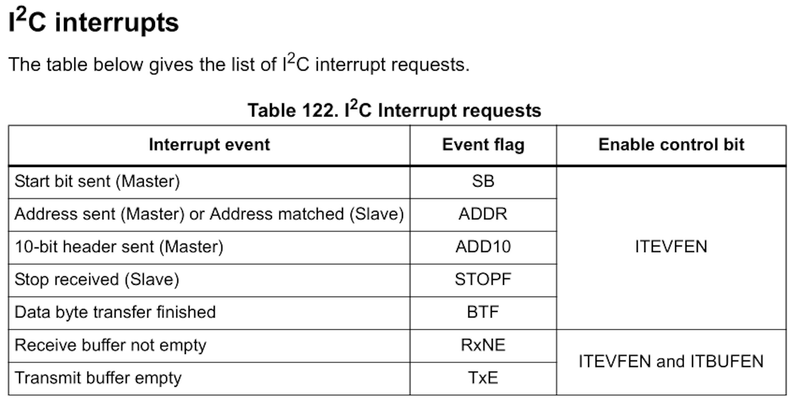
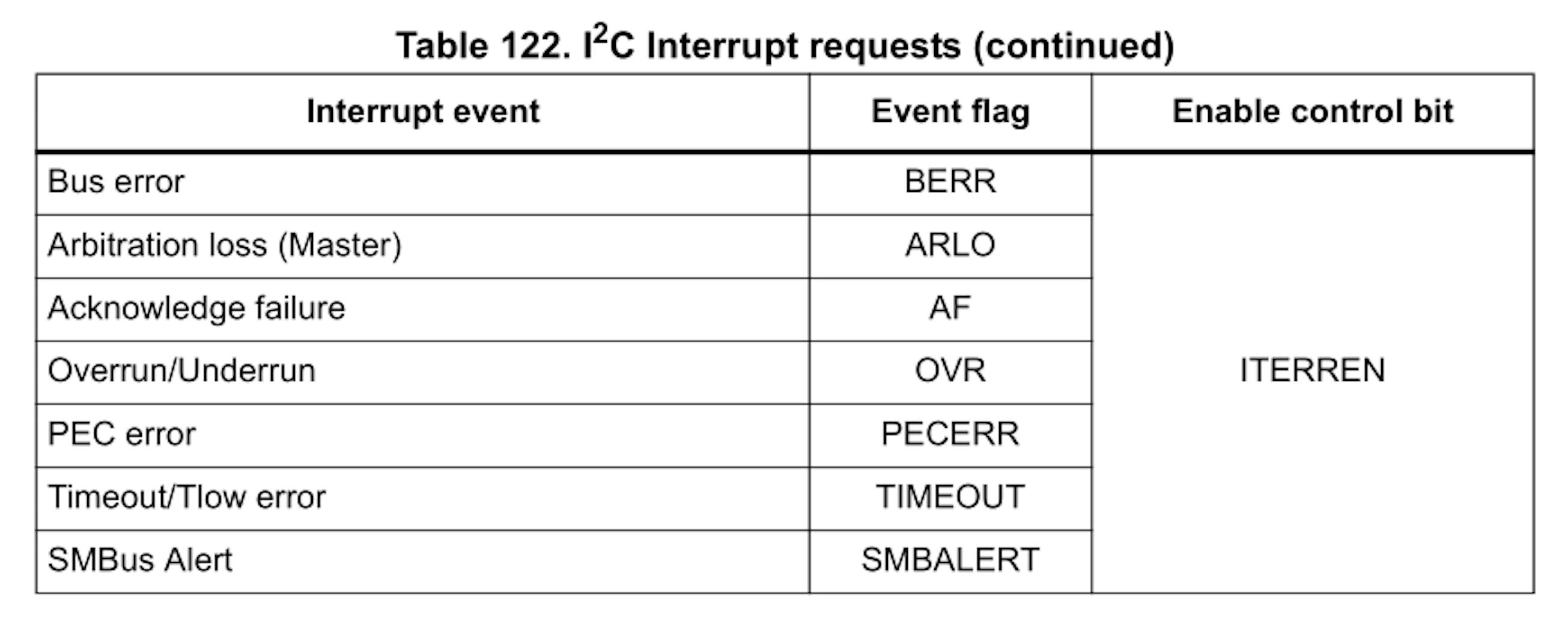
So, what does typical I2C data reading look like? Well, something like this:
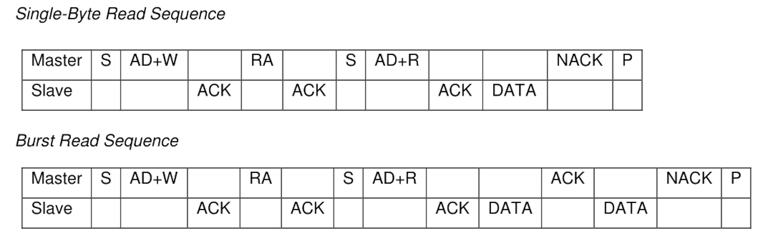
It doesn't seem complicated, right? That is what we do:
- Generate START (S).
- Wait for the SB bit set (interrupt or polling doesn't matter).
- Send the address of the device with which we want to communicate and a sign that we will write to the device.
- Receive ACK from that device.
- Send the register address that should be read.
- Receive ACK.
- Resend START, so that another master does not take control of the line.
- Send the address of the device, but this time with a sign that we will read from the device.
- Read data.
- After the last received byte, send NACK and generate the STOP condition.
A very simple algorithm that drank all my blood and entertained me for a whole week. Devil is hidden in the details :) The very first thing I encountered was that before point 1, there should be point 0 — wait until the I2C line is free. In this expectation, the fun part is that this particular model can hang there immediately after power-up, forever. Errata says that this is due to incorrect operation of the I2C analog filter, and there is a workaround. It first starts the timer, which turns off as soon as the line becomes free. In case the timer is interrupted, then most likely the line is busy, and you must act as described in errata.
I decided to use asynchronous reading and writing of data on I2C. First of all, synchronous reading stopped working after 20 seconds — the controller was hanging dead. Of course, the errors were in the external library working with the MPU6050, but still, it was somehow unpleasant. Moreover, each of the sensors has a sign that the data is ready and can be read. They even generate interrupts that signal data readiness, so it was a sign not to use such a mechanism. Also, unload the controller for other things that never hinder. For this, a simple state machine was implemented:
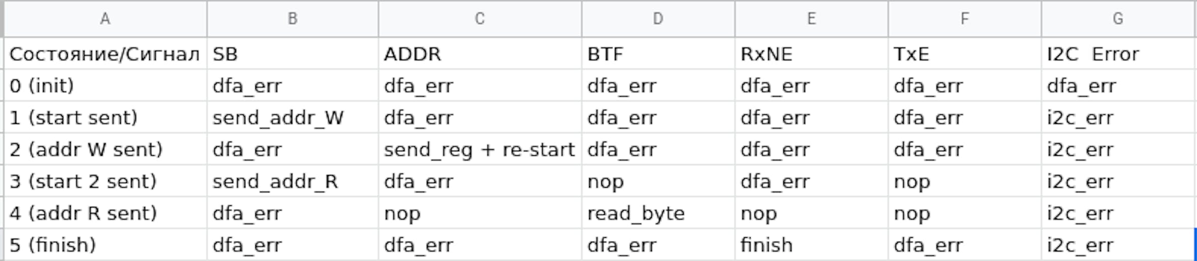
Initially, the state machine is in the init state. As soon as you need to start receiving any data, a START condition is generated. Then everything is processed in interrupts. It seems to be nothing complicated either. However, there is a problem I did not find any explanation for, which can be reproduced like this:
- Generate START
- Everything works fine before state 2. Then, the restart condition is generated in state 2.
- After a restart, an interrupt occurs, but none of the I2C interrupt flags are set. Well, that is not a flag at all. There are no error flags, no flags from the interrupt table above. However, the following reading of the SR register explains that the SB flag is still set.
Actually, when there is no interrupt flag, it is rather difficult to handle it. :) In our case, I just used the mask of all possible interrupts. If none match, the interrupt is ignored. There is some explanation on the STM forum. It says that when a START condition is re-generated, an "early" interrupt is generated with all the flags cleared. I2C implementation peculiarity in STM32F100x controllers. I decided for myself that the interrupt request arrives faster than the SB flag is set, and when I ignore such an interrupt, the interrupt flag is not cleared. A repeated interrupt is generated, the flag is already set, and everything works fine.
Well, the second issue is that you need 2 different state machines for reading data. If the number of bytes N ≥ 2, you need to use the state machine shown above. If N < 2, then you need to disable ACK and generate STOP immediately after the device address with the read flag is sent. Then the slave will send 1 byte, after receiving which the controller will not send an ACK to it and generate a STOP.
The conclusion is that you should always carefully read the documentation for the controller and its errata. For example, the first versions of the automaton worked on the RxNE event, but only if there were no interrupts from other sources. If interrupts from timers, USART, etc. are added, the state machine falls apart due to the setting of the BTF flag. Setting the highest priority for I2C interrupts (as mentioned in errata) does not solve this issue.
What's wrong with the magnetometer?
Having solved all I2C issues, I began to confidently receive data from the accelerometer, gyroscope, and magnetometer. Seems that everything is ready, and I can feed the data to the Madgwick filter, get a quaternion, and calculate the required rotation angle. But everything went wrong again. :) Arrow stubbornly showed in any direction but not to the store, 500 meters from the office, which I used as a test destination point. At the same time, an application written for Android worked fine. By the way, developing an application for Android, covering all with unit tests, and making sure that the whole math works was a very good idea. Trying to spot the issue, I displayed the magnetometer data on the display. It immediately became clear that the magnetometer was not calibrated. In general, I was very surprised that when the X axis is directed to the north, the magnetometer shows one value. If you turn Y in the direction of the north, then the magnetometer gives a completely different value from X. At first, it seemed that it made no sense, but everything can be explained simply.
There are two types of distortion acting on a magnetometer. The first is called Hard Iron Distortion. By its nature, it is additive, that is, an additional one is created by a permanent magnet (in my case, a transistor and other elements on the board), which is added to the initially measured field. With a constant orientation of the magnet relative to the sensor, the offset introduced by them will also be constant. The second type is the Soft Iron Distortion. It is created by foreign objects that distort the already existing magnetic field.
Fixing hard iron distortion is easy. To do this, you need to rotate the device around the Z axis several times and get the minimum and maximum values for each of the magnetometer axes. Then do the same with the Z axis of the magnetometer (i.e., rotate the device sideways and twist around the X or Y axis). Having obtained the maximum and minimum values along the axes, we calculate the bias as (Max — Min) / 2. Initially, I moved the magnetometer by eight degrees, but this method gave worse results than described above. Apparently, in my region, the vertical magnetic deviation is large.
The distortion of soft iron is more difficult to compensate for. Basically, it is proposed to use the Mag Master application, with which you can get a compensating matrix and offset values. But first, it is written in C # and works with Windows only. Secondly, you need to refine your firmware in order to work normally with this program. So we will do something not quite as sophisticated but in the same spirit. We will take the min/max values already computed and use them to rescale the magnetometer data to equalize the response along the three measurement axes.
#define MagXMin 1880
#define MagXMax 5547
#define MagYMin 6185
#define MagYMax 10157
#define MagZMin -6530
#define MagZMax 5305
#define MagXBias ((MagXMin + MagXMax) / 2)
#define MagYBias ((MagYMin + MagYMax) / 2)
#define MagZBias ((MagZMin + MagZMax) / 2)
#define MagXAvgDelta ((MagXMax - MagXMin) / 2.0f)
#define MagYAvgDelta ((MagYMax - MagYMin) / 2.0f)
#define MagZAvgDelta ((MagZMax - MagZMin) / 2.0f)
#define MagAvgDelta ((MagXAvgDelta + MagYAvgDelta + MagZAvgDelta) / 3.0f)
#define MagXScale (MagAvgDelta / MagXAvgDelta)
#define MagYScale (MagAvgDelta / MagYAvgDelta)
#define MagZScale (MagAvgDelta / MagZAvgDelta)
mx = (float)(m_magRaw.data.mx - MagXBias) * MagXScale;
my = (float)(m_magRaw.data.my - MagYBias) * MagYScale;
mz = (float)(m_magRaw.data.mz - MagZBias) * MagZScale;
Thus, the data from the magnetometer came in a more or less normal form. In any case, now with the rotation of our device and visualization of the data obtained, we obtained a figure resembling a sphere instead of 3 different ellipses.
However, in the final version of the firmware, a 3x3 matrix will be used to correct the readings of the magnetometer.
Magnetic declination
In fact, I knew that I would have to do something with magnetic declination. The essence of this phenomenon is that the magnetometer does not show the real north, but the magnetic north. And the difference between these directions is called magnetic declination.
The National Geospatial-Intelligence Agency (NGA) provides the source code of an application written in C to determine the value of magnetic declination based on WMM (World Magnetic Model). It also provides a data file that is updated every 5 years. If last time I didn't have to think about it (Android has already implemented the calculation of magnetic declination), then this time I had to deal with the code that this agency provides. A little confusing, but after refactoring, everything fell into place, and we were able to adapt it for use on the microcontroller.
After taking into account the magnetic declination, the readings of the arrow become even more accurate. In my city, this is only 5 degrees the difference, but in Moscow (for example) it is already a noticeable 11 degrees.
Result
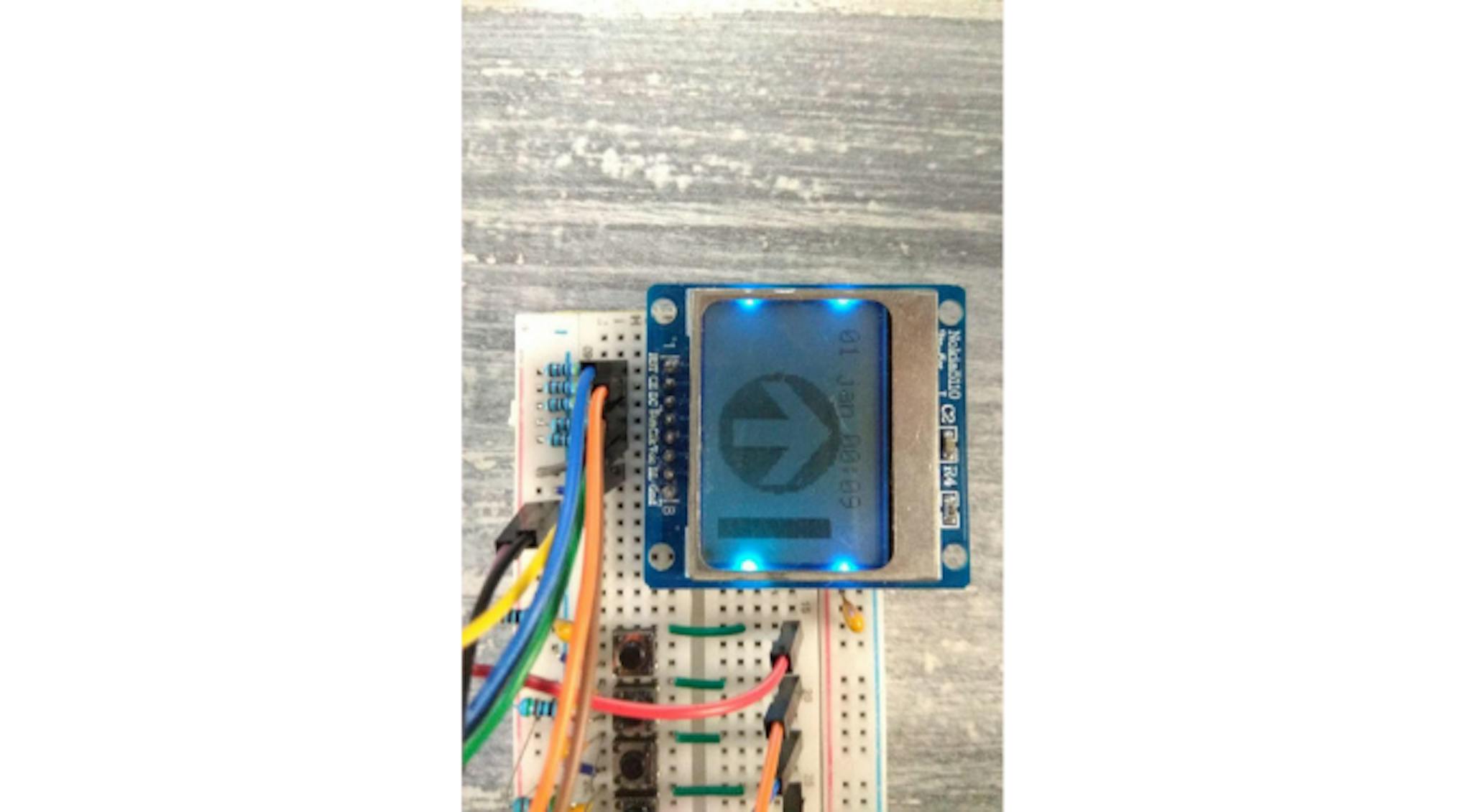
Attempting to demonstrate that the arrow really points in one direction while rotating the device
As a result, there is such a prototype and a variant welded together on a breadboard. From the remaining work:
- Normal menu for settings. It is necessary to allow them to change their time zone.
- Add the ability to conveniently calibrate the device.
- Finish PCB and order a couple of copies.
Use and develop
Link to the repository: mad-navigator
For questions and improvement suggestions please create issues in our repository (see link above).
This solution is distributing under MIT license. Use it and don't forget to place copyrights. :)
References
- Magnetometers: Principle of Action, Error Compensation — hard and soft iron distortions description (russian language).
- Teslabs Engineering: Magnetometer Calibration —most detailed soft and hard iron distortion description with compensation examples written in Python.
- Calibrating an eCompass in the Presence of Hard- and Soft-Iron Interference — the technical description of soft and hard iron distortion.
- How to Calibrate a Magnetometer? —a most simple description of soft and hard iron distortion.
- The following 3 materials explained the mistakes made when building the layout at the initial stage and helped to fix them (russian language):
Power Layout
How to Connect LEDs to a Computer
EMI-Resistant Devices - Open source IMU and AHRS algorithms — everything related to Madgwick AHRS with implementation.
- Geomagnetic Calculators, Maps, Models, and Software — model and code for magnetic field characteristics calculation.


Latest articles here