

Analyze with AI
Get AI-powered insights from this Mad Devs article:
Hello everyone!
In this article, we will cover the main methods of simulation and firmware testing for AVR microcontrollers.
Why do we need to test AVR microcontrollers?
Any testing of the software is necessary in order to make sure that the program is working. Testing also ensures that the program or certain parts of it meet specific requirements. However, passed tests do not guarantee a complete absence of errors in the project. They only increase the probability of issue detection at early stages of development.
An error during compilation has zero cost. At the stage of initial testing, the error cost is equal to the cost of the developer's time. At the stage of alpha or beta testing, the cost of errors is increasing. The price of fixing errors found after launching a product in a series can cover the cost of the entire project. You are lucky if it's just about releasing a hotfix (though it might be not so easy for hardware projects). In the worst case, you will have to revoke the whole batch. The main purpose of testing is to save money and time.

Comparison of testing in software and hardware projects
Software testing is performed on standardized hardware at a high level of abstraction. The standard environment and ready-made test frameworks allow for unambiguous test results, regardless of the hardware on which the product is running.
The situation with the testing of microcontrollers (and hardware devices in general) is simpler but still quite confusing. Testing is easier because microcontrollers are mainly designed for simple tasks. The examples of such tasks are LED blinking, sensor data gathering, simple data processing, controlling display output, and communication with other peripheral modules. The main difficulty is that the environment where the program executes depends on the model and manufacturer of the controller. Firmware runs at the low level. Given the stringent performance requirements, testing becomes a daunting task.
What kind of testing can I use depending on the task?
There are three main options for running tests on embedded systems. Let's list them all:
- Local testing on the host machine
Advantages: Tests start and work quickly, no need to access the device.
Disadvantages: Limited testing area. It will not work with external peripherals. A good example of using this method is the testing of a platform-independent computational algorithm that requires a dataset from sensors. The testing of such an algorithm with a real data source would be very inconvenient. It's much better to prepare a dataset in advance. You can do this by using a small logger program on your unprocessed sensor data. - Testing the MCU in simulation
Advantages: No device needed for testing. You can program your environment for the MCU.
Disadvantages: Limited accuracy of the MCU and environmental simulations, difficulty in creating and configuring such an emulator. - Testing the firmware on the real MCU
Advantages: It is possible to work with the periphery of the MC; the firmware will work out the same way as in production.
Disadvantages: You need to have a ready-made device with all peripherals and electronic components. The test cycles will take a long time due as you will have to constantly reflash the MCU. It is very difficult to automate testing using this method.
In this article, we will analyze the first two methods as the most promising for automation.
Local testing
Local tests are very good for testing the firmware parts that are not dependent on the environment. Examples can be any computing algorithms, various containers, lists, queues, trees, high-level exchange protocols, finite machines, etc.
Let's consider an example for AVR microcontrollers with the possibility of local testing of the platform-independent firmware parts.
Testing firmware compatible with AVR MCU
For AVR MCU, the most convenient and productive development environment is Atmel Studio. Unfortunately, this environment is not cross-platform and is only available for Windows.
For a clear comprehension of examples in this project, I use open-source tools. I rely on VSCode on Ubuntu for source code, AVR GNU Toolchain for compiling, and linking firmware, gcc for compiling tests, and the simulator.
The project build process (compile, link, firmware) is done with the make utility. This approach allows me to automate test execution and firmware upload to the target system.
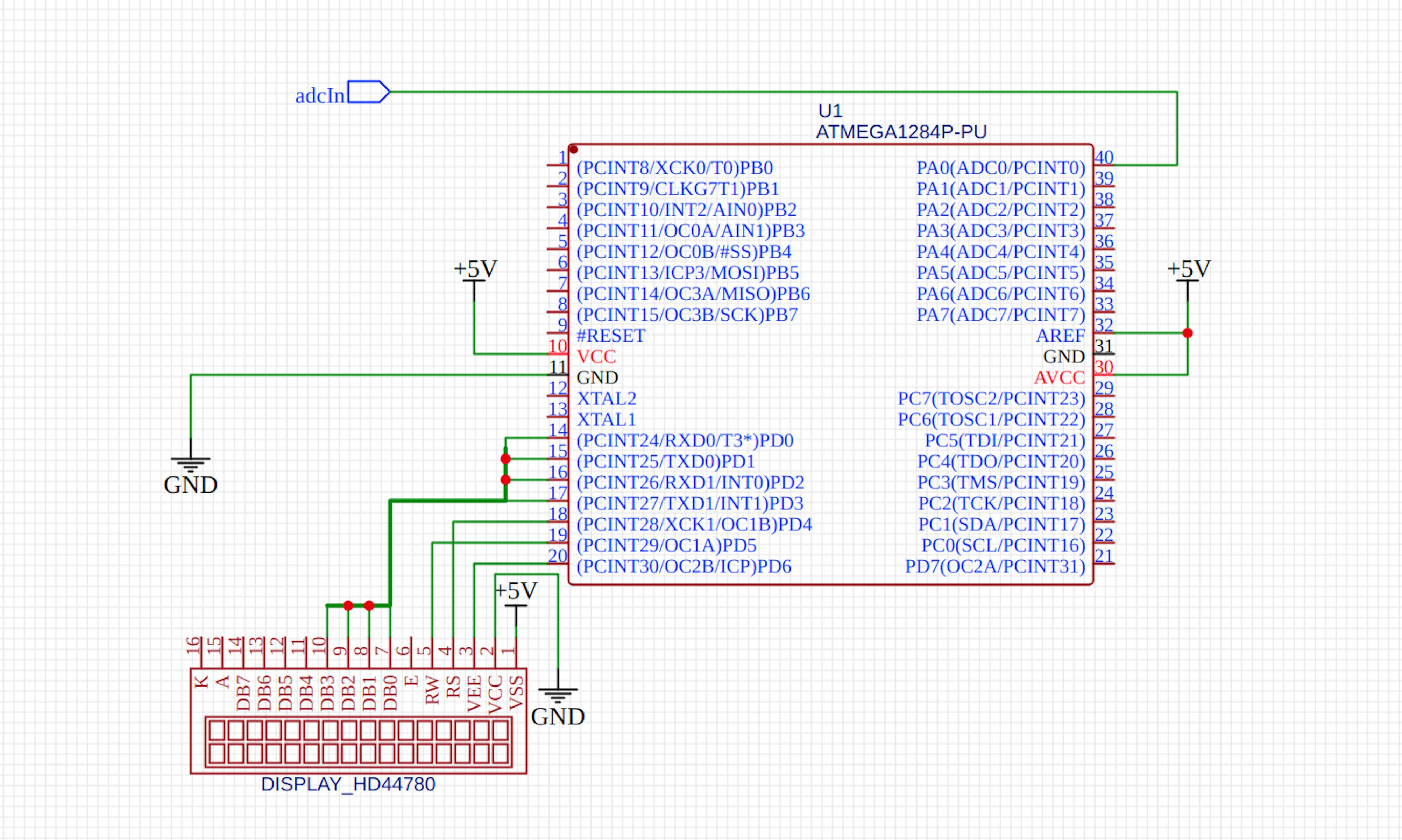
For example, let's consider the firmware for the Atmega1284 microcontroller that implements the functionality of a simple thermometer.
Temperature measurement is performed by reading the voltage on the voltage divider (which includes a thermistor), converting the ADC value into temperature values, and displaying them on the 1602 (HD44780) LCD screen.
The function of communication with the internal and external periphery can be performed via operating the microcontroller registers.
Nevertheless, our firmware has functionality which it is necessary to test (converting ADC value into temperature and then displaying it on the LED screen).
Let's consider an example of native testing of the firmware functionality.
You will need the AVR GNU Toolchain to compile.
To create a project with tests, you need to separate sources by function. What runs only for MCU should not be mixed with source files that can run on local systems. That is not an easy task. Also, you should use two compilers, making some modules platform-dependent and others not. Let's look at main.c for more details.
GitHub Gist is loading...
In local testing there are two sections of main.c:
- For testing functionality.
- For implementing the main program cycle.
Let's consider testing conversion of ADC values to temperature (src/tests/test.c file):
GitHub Gist is loading...
When implementing such a test, it is necessary to split the Makefile into two sections: the first section will use a compiler from AVR Toolchain — avr-gcc (compiler for AVR microcontrollers), and the second section will use gcc for compiling the platform-independent executable files.
This example enables you to test the functionality of converting ADC values to temperature using calculated temperature values depending on the input voltage of the microcontroller. When you change the conversion functionality, you just need to run the tests and make sure that they have not detected any errors.
To compile and run the tests, do the following:
after a successful compilation, the executable test file will appear in the AVR_Testing/builds/tests/ directory.
Native test development is quite a huge task, and implementing it takes a lot of time. Therefore, it will be more productive to use one of the existing frameworks for testing.
Testing with Unity framework
Let's run the same tests using Unity, a simple framework for testing of embedded systems.
In the same project repository (the unity-framework branch) you will find an example of the framework usage.
When using Unity, the compilation of tests and firmware is done separately, like in native tests. The testing of each module has its own entry point and can be run independently if you use Unity.
To start using the framework, simply clone the framework's repository.
Ruby is used to generate sources of an executable file from a test case file. To install it, do the following:
Another remark: to use unity in your project, you need to specify the absolute path to it in the variable $(UNITY_ROOT) of your Makefile.
An example of a testcase source:
GitHub Gist is loading...
In this example, we only need to specify the header file of the sources of the module under test and implement the verification of the operation of converting ADC values to temperature with the acceptable value for the observational error.
Besides writing test cases for Unity and specifying the path to the framework, you should also add special compiler directives.
In this case, we use a comparison of numbers with a floating point of increased accuracy. Testing of double types is disabled in the framework by default; you need to add directives to enable the double types:
After you hit make tests, Ruby will generate test entry point files, which will get compiled and run.
Simulator using testing
In most hardware projects, the microcontroller is used to interact with external and internal peripherals, whose behavior is very difficult and sometimes impossible to simulate during tests. Target system simulators are very helpful in solving this problem.
For microcontrollers with AVR architecture, there are several simulation systems listed below:
- Atmel Studio is the development environment for AVR microcontrollers that I have mentioned earlier. (The one that works only for Windows.) It includes a built-in simulator for almost all AVR microcontroller models and a handy toolkit for creating and controlling both internal and external peripherals. The drawback is the lack of cross-platformity and the cumbersomeness — it's hard to automate the simulation.
- Simulavr is an open-source, cross-platform C/C++ project that offers its own AVR microcontroller simulation systems. There are several models of microcontrollers, with the ability to write debug scripts in Tcl/Tk and Python. The disadvantages are the complicated mechanism of adding new MC models to the simulator, complex documentation, and the fact that the project remains unsupported for several years.
- Simavr — relatively new (and at the same time quite flexible) cross-platform project for writing AVR MCU simulators in C/C++. Because of the similar name, it can be confused with the previous tool; however, these are completely different projects. Simavr has a large number of AVR MCU models, and the architecture enables you to easily add new devices and models. It also has integration with PlatformIO (VSCode extension for embedded systems development) and clear examples of how to use the tool with different kinds of peripherals. Disadvantages: the lack of a description of the project build, and rather obscure documentation.
I chose the Simavr as the most promising option.
To start using Simavr, just clone and build the repository.
After a successful build, you can test the simulator's performance by running tests or examples. To run the executable files of this simulator, you need to create a symbolic link to the sources in the firmware directory. For example, in the simavr/tests directory:
Here's the symbolic link for executable file creation:
In the simavr/examples, you will find folders with sources of simulations, and the parts folder contains the sources of common peripherals.
For a more immersive effect, you can run examples with graphics, such as board_hd44780, board_ssd1306.
Simavr provides a wide range of tools for the following types of tasks:
- Development of custom virtual boards with microcontrollers and peripherals.
- Development of virtual electronic components.
- Managing simulation behavior on time segments up to microcontroller tact.
- Connection of avr-gdb debugger.
A full description of the simulator's features can be found in the project repository.
Structurally, any simulator on a Simavr represents sources of board, peripherals, and compiled firmware (by the way, a Simavr simulator enables you to load the same firmware as on a real device, changes are not required).
For the example of testing, let's look at the tests of the same thermometer while using a simulator (see the simavr-testing branch).
The structure of src/tests/sim directory is as follows:
Schematic of the virtual board:
Simavr has a very simple, though not quite obvious, project structure.
Let us have a look at the most important moments of a board implementation:
main_wrapper.c is the wrapping of the entry point for firmware. It provides the compiler and the simulator with additional information about firmware, power supply voltage, and other parameters (full description of all parameters can be found in simavr/simavr/sim/avr/avr_mcu_section.h).
GitHub Gist is loading...
adcToLcd.c contains sources of the board as well as descriptions for manipulations with the periphery, data ports and operating time intervals between actions of the periphery.
GitHub Gist is loading...
When initializing firmware, the board searches for the specified firmware ELF file, then creates the MCU and uploads the firmware to it.
To initialize and work with the display, in the parts directory, find the sources of the LCD screen on the HD44780 controller. For the project, I just took them from simavr/examples/parts and refactored the function of displaying the data on the screen for parsing and returning a double value.
Next, the function of connecting peripheral parts to the setConnections controller is applied, which uses such methods as:
— It returns a pointer to the unique identifier of the I/O port PIN. Arguments are the controller identifier, port, and PIN.
(See simavr/simavr/sim/sim_io.h for details).
— This is the function of connecting one PIN I/O (peripheral or microcontroller) to another.
The example of a use for this function:
— Сonnecting PORTD PIN 4 of the MCU to the RS PIN of LCD.
You can raise signals to be sent to the I/O ports using the following function:
— It accepts the port identifier and the required value. Value can be equal to 1 or 0 for digital inputs, or store a value in millivolts for analog inputs.
Simavr has a convenient mechanism for setting the time for external events by registering timers. On triggering the timer, a callback function is executed.
There is a function for registering the timer:
— It accepts the controller identifier, the actual time after which the timer will trigger, the callback that will trigger, and its optional parameters.
In our board, the callback performs the function of reading the screen output, switching to the ADC output of the next voltage value, and registering a new timer. For adequate reading of information from the screen, the board uses a timer setting the delay until the display is filled with new data.
To perform every tick of the MCU, please use:
— Using this mechanism enables you to suspend the simulation for some time to verify the data or perform calculations. It also serves as a mechanism for launching the simulator in a separate thread.
In our example, we use a simple implementation by simulating a single thread, collecting the simulation results, and testing the collected data.
In order not to overload the code with two testing methods, it was decided to put the test case into a separate file adc-temp_test.c, which connects to the project both when compiling tests on Unity and when using the simulator.
To compile and run the simulation, just specify the absolute path to simavr in src/tests/sim/Makefile, in the $(SIMAVR) variable, and execute it in the src directory:
Unlike modular tests, tests using a simulator (in fact, these are integration tests) allow for full evaluation of the correctness of firmware operation.
Simulation of ADC conversion is a clear example of the quality of testing in our project. Due to the limitations of ADC discretization, when calculating low values, the simulation has considerably observational error than it is found during the unit tests.
For larger projects, you can easily integrate the simulator with the Unity framework and automate the testing process via CI/CD.
Testing the firmware on real hardware
The launch of hardware tests is mostly done manually, using on-chip debugging systems such as JTAG.
To automate hardware tests, it is necessary to emulate the behavior of the external periphery using another microcontroller. The adequacy of the behavior of the emulated periphery is questionable. In this case, the test might even be more expensive to write than the firmware itself. Anyway, this approach ensures maximum accuracy and closeness to real conditions. Description of test preparation methods deserves a separate article, and we will tackle this topic in the next publications.
Conclusion
There is a lot more to tell about firmware testing. There is no standard method for testing platform-dependent code. However, general recommendations when writing tests and simulators for specific models of AVR microcontrollers allow for fully automating the firmware testing process. I hope this article has helped you acquire basic knowledge about the testing of AVR microcontrollers.


Latest articles here